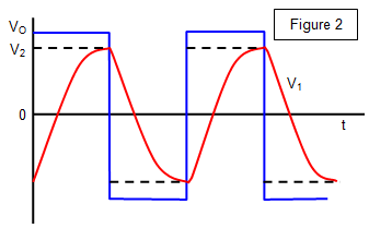
The op amp voltage comparator may be used as an oscillator if positive feedback is used. The circuit and waveforms are shown in Figures 1 and 2.

Suppose that the output voltage is positive at a particular instant. A certain fraction b of the output voltage (Vo) is fed back to the non-inverting input, and Vo is fed back to the inverting input via R1.
After a certain time that depends upon the time
constant CR1, the voltage at P exceeds that at Q, that is, V1 >
V2. The op amp therefore switches to negative saturation (Vo = - VS) and as a result of the
positive feedback Q becomes negative.
The capacitor (C) now charges in the opposite direction,
and the voltage at P falls until V1 < V2, at which point the op amp switches
to positive saturation and the cycle repeats itself. The output voltage is therefore a square wave, as can
be seen from the graphs in Figure 2.
The equation for the frequency (f) of such a system is:
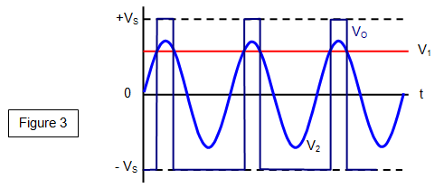
If the input to the non-inverting input is a sine wave, then the op amp will saturate
every time the difference between the voltages at the inverting input and the non-inverting input exceeds
about 150 μV.
The saturation will swing from positive to negative as this voltage difference becomes
positive or negative.
This will result in a square wave output, as shown in Figure
3.