
This particular integrated circuit has
come to have wide applications because of its very high gain, its ability to carry out simple
mathematical functions such as addition and subtraction, multiplication, differentiation and
integration, and its use as a voltage comparator circuit or oscillator.
It is particularly useful
because of its following properties:
(a) very high open loop voltage gain (Ao) - up to 105 (100
000) for d.c. - although this does decrease with frequency (see later)
(b) a very high input
resistance so that it draws virtually no current from the input signal;
(c) a very low output
resistance
(d) it is a differential amplifier, giving an amplified output signal proportional to the
difference between the two input signals providing that this difference is not too large (see
later).
A common form of op amp used in schools is the type 741. This is made in what
is called an 'eight-pin dual in line form' and is shown diagrammatically in Figure 1 together with
the symbol for an operational amplifier (shortened to the words op amp.)
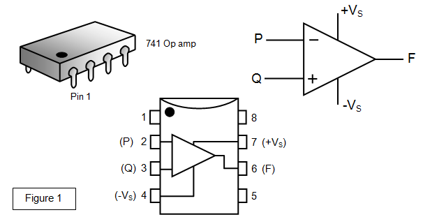
Of the eight pins
on the op amp we are interested in only five:
(a) the inverting input (P) - inputs here will be
changed in sign (pin 2)
(b) the non-inverting input (Q) - inputs here will not be
changed in sign (pin 3)
(c) the output (F) (pin 6)
(d) the positive supply (+VS) (pin
7)
(e) the negative supply (-VS) (pin 4)
We will call the voltage at the inverting
input V1 and that at the non-inverting input V2.
The positive and negative supply connections
are shown on the above diagram but they will be assumed and omitted from the following
circuits.
The internal circuitry of an op amp is complex and outside the scope of this
section of work (the 741 contains twenty transistors, eleven resistors and one capacitor). We
shall treat it as a 'black box' that will perform certain functions if connected into a circuit
correctly.
The circuit symbol represents an 'open loop' amplifier with an 'open loop gain'
Ao.
The output potential (Vo) is proportional to the DIFFERENCE in the potential between P
and Q (i.e. to [V2 - V1]). Where V1 is the input at the inverting input (P) and V2 is the input at the non-inverting input (Q).
In fact it is given by the equation:
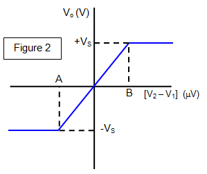
This is true providing the output potential is less than that of the
supply voltage VS. When Vo reaches VS the op amp is said to be SATURATED. This can be
seen from Figure 2 which is known as the transfer characteristic for the op amp.
Te
output voltage lies between + VS and – VS. The supply voltage used in most examples in this
book is 15 V and so Vo must be between +15V and -15V.
You can see that there is a small
region between A and B where the graph rises linearly and it is in this region that the op amp is
operated as an amplifier.
Since Ao is about 100 000 the op amp will saturate for a
difference of potential between P and Q of more than 150 μV. (100 000 x 150x10-6 = 15 V)
If
the difference is more than 150 μV the output will be +15 V if V1 < V2 and -15V if V1 >
V2.
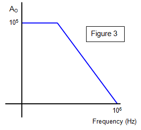
The open loop gain varies with frequency and this is shown in Figure 3. As the frequency of the input signal increases so the open loop gain falls. This can be explained by the decreased mobility of the charge carriers through the semiconductor material.
An
important property in various areas of Physics, particularly in electronics is that of
feedback.
Feedback is the term used to describe the situation where a certain fraction
of the output of a device is fed back to the input.
There are two types of feedback:
(a)
negative feedback - this tends to reduce the output. A simple example of this is the flow of silty
water through a hole. The slower the flow the more silt settles and the quicker the hole fills up
and the slower the rate becomes and so on;
(b) positive feedback - this tends to increase
the output. This is shown by a snowball rolling down a hill, the bigger it is the more snow it picks
up and the bigger it becomes, and so on.
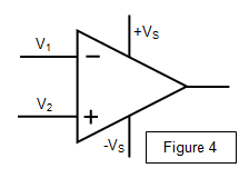
where V1 is the inverting input and V2 is the non-
inverting input (Figure 4). The voltage difference between the two inputs is therefore amplified
and appears at the output.
Alternatively, we can regard the circuit as one in which
voltage 1 is amplified, voltage 2 is inverted and then amplified, and the difference between
these final voltages is
found.