

The transformer uses the property of mutual inductance to
change the voltage of an alternating supply. It may be used in the home to give a low-voltage output
from the mains for a cassette recorder or train set, or in a power station to produce very high voltages
for the National Grid. It is important to remember that transformers rely on changing magnetic flux and
will therefore not work with d.c.!
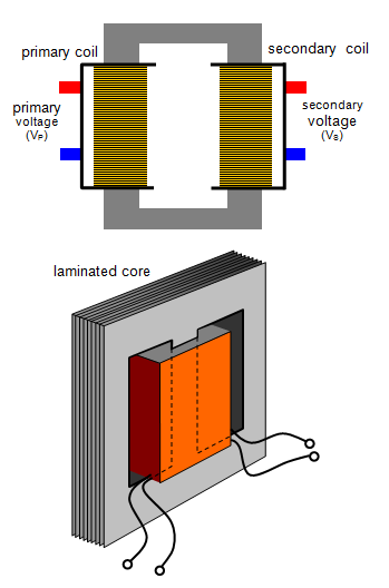
In its simplest form a transformer consists of two coils known
as the primary and secondary, wound on a laminated iron former that links both coils. The former, or
core as it may be called, must be laminated otherwise large eddy currents would flow in it. The
laminations are usually E-shaped, and the primary and secondary are wound one on top of the other
to improve magnetic linkage.
An a.c. voltage is applied to the primary and this produces a changing magnetic field within it. This changing magnetic field links the secondary coil and therefore induces an e.m.f. in it. The magnitude of this induced e.m.f. (Vs) is related to the e.m.f applied to the primary (Vp) by the equation:
where np and ns are the
number of turns on the primary and secondary coils respectively. The negative sign means that the
voltage induced in the secondary is 180o (or p) out of phase with that in the primary. If the output
voltage is greater than the input voltage the transformer is known as a step up transformer and if the
reverse is true it is called a step down transformer.
The current in the secondary produces its
own magnetic flux, which is opposite to that of the primary. When the current in the secondary is
increased, by increasing the load, the flux in the core is reduced. The back e.m.f. in the primary
therefore falls and the current in the primary increases. Eventually the situation will
stabilise.
The output voltage may be measured with a meter but a better method is to use an
oscilloscope since it draws no current from the transformer. (Digital meters with a resistance of many
MW are also suitable)
We have assumed here that there is no leakage of flux, that is, that all the
flux produced by the primary links the secondary and that there are no energy losses. In practice,
however, energy is lost from a transformer in the following ways:
(a) heating in the coils - this can
be reduced by cooling the transformer, usually in oil;
(b) eddy current losses in the core - reduced
by the laminated core already mentioned;
(c) hysteresis loss - every time the direction of the
magnetising field is changed some energy is lost due to heating as the magnetic domains in the core
realign. This is reduced by using a 'soft' magnetic material for the core such as permalloy or silicon-
iron. For soft magnetic materials the loss might be about 0.02 J per cycle.
Despite these energy
losses transformers are remarkably efficient (up to 98 per cent efficiency is common) and they are in
fact among the most efficient machines ever developed.
If we now assume the transfer of energy
from primary to secondary to be 100 per cent efficient, then
power in primary = power in
secondary and therefore:
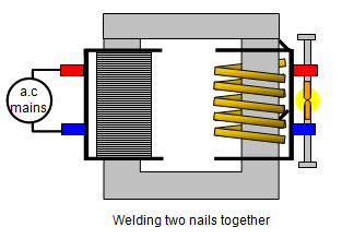
In the first experiment the secondary coil is of only six turns and is shorted by a
nail. When the power is switched on the current in the nail is so great that it melts. An arc can then be
struck between the two broken ends, so welding them together again.
In the second experiment the secondary is simply an
aluminium trough which contains water. When the power is switched on the current in the aluminium is
so great that the water boils!
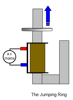
Another fascinating demonstration is the jumping ring. This is
more effective if cooled in liquid nitrogen or even using solid carbon dioxide. Extending the core of the
transformer also makes it jump higher.