Wheatstone bridge
The Wheatstone bridge, devised in 1843, provides
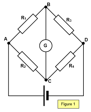
an accurate method of determining the resistance of an unknown resistor. The circuit is
shown in Figure 1. Four resistors are joined as shown, one of them being an unknown
resistor whose resistance is to be measured and one a standard resistor. We will assume
that R4 is the unknown. R3 can be varied and it is adjusted
until no current flows in the galvanometer.
In this condition:
p.d. across AB = p.d. across AC and
also
p.d. across BD = p.d. across CD
Therefore: I
1R
1 =
I
2R
2 and I
1R
3 =
I
2R
4
Balance condition: R1/R3 = R2/R4
The arms AB and BD are known as the ratio arms of the bridge.
It can
be shown that for the highest sensitivity the galvanometer must be connected from the
junction of the highest resistances to the junction of the lowest. The accuracy of the
Wheatstone bridge should be of the order of 0.2%.
A
switch is usually incorporated in the circuit in series with the cell, to prevent current flowing
through the bridge at points other than the balance point and thus heating the components
and changing their resistance.
Example problems
A short occurs in a telephone cable having a resistance of 0.45 Ω per metre. The circuit is tested with a Wheatstone bridge. The two resistors in the ratio arms of the Wheatstone bridge network have values of 100 Ω and 1110 Ω respectively. A balance condition is found when the variable resistor has a value of 400 Ω.
Calculate the distance down the cable where the short as occurred.
Let the total resistance of the two parts of the cable be R.
100/1110 = R/400 Therefore R = 36.04 Ω.
Therefore distance down the cable = 36.04/[2x0.45] = 40 m
A VERSION IN WORD IS AVAILABLE ON THE SCHOOLPHYSICS USB