We are all familiar with the electric spark formed when a high-voltage
discharge occurs across a region of air, and also with the bright yellow light emitted by a
sodium vapour lamp. Both these are examples of the conduction of electricity through gases
- the differing results being due not only to the different gases but also the different
pressures under which conduction takes place. (The pressure in a neon lamp is about 10
mm of mercury.)
The effects of different gases are considered elsewhere and we
will consider here only the effect of pressure changes on the discharge in air.
In dry air at atmospheric pressure a voltage of 30
kV is required to produce a spark between two spherical electrodes 1 cm apart. (For pointed
electrodes the p.d. is reduced to 12 kV due to the higher field at a point.) In a thunderstorm,
even allowing for the moisture in the air, you can appreciate the truly enormous voltages that
are required for one lightning flash. For small potential differences, a gas is an almost
perfect insulator.
At lower pressures however the potential difference to give
sparking is reduced. This is because the mean free path of the electrons (distance that the
electrons travel between collisions) is longer and they can therefore be accelerated to higher
speeds before collision with an atom; they therefore have more chance of causing
ionisation.
The following table shows the mean free path (in metres) of an electron
in various gases at different pressures.
The pressure is given in mm of mercury. (760
mm is a pressure of about 105 Pa.)
| Gas | Pressure | |||
| 760 mm | 10 mm | 1 mm | 0.001 mm | |
| Hydrogen | 1.83x10⁻⁷ | 1.4x10⁻⁵ | 1.4x10⁻⁴ | 0.14 |
| Oxygen | 9.95x10⁻⁸ | 7.56x10⁻⁶ | 7.57x10⁻⁵ | 0.076 |
| Nitrogen | 9.44x10⁻⁷ | 7.17x10⁻⁶ | 7.17x10⁻⁵ | 0.017 |
The discharge through gases at low pressure may be investigated using a Geissler tube. This is simply a glass tube containing air, the pressure
of which may be varied, with electrodes at either end. It is unsafe to use a Geissler tube with
applied potential differences above about 5-6 kV, because above this voltage X-rays may be
generated by the impact of electrons with the anode and walls of the
tube.
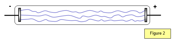
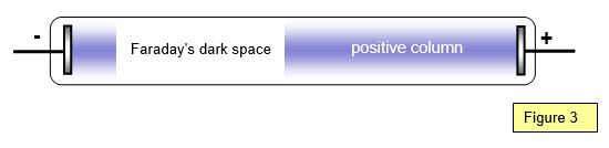
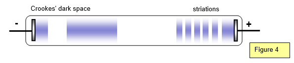
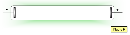
Figures 2 to 5 show the appearance of the discharge in air for various
pressures.
At 20 mm pressure, violet streamers pass between cathode and anode
(Figure 2).