Reactance
The term reactance is given to the effective resistance of a
component to a.c. It is given the symbol X and is defined as:
X = amplitude of
the voltage across a component/amplitude of
the current flowing through it
(a) For a capacitor, i = ωCV
giving
Reactance of a capacitor = XC = V/ωCV = 1/ωC = 1/2πfC
The reactance of a
capacitor is therefore inversely proportional to the frequency of the applied p.d. (since ω = 2πf).
(b) For an inductor, V = ωLi
giving
Reactance of a inductor = XL = VωL/V = ωL = 2πfL
The reactance of an
inductor is therefore directly proportional to the frequency of the applied p.d.
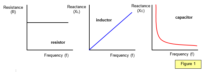
The
variation of the resistance of a resistor and the reactance of an inductor and a capacitor
with the applied voltage frequency (f) is shown in Figure 1.
Example problem
Calculate the reactance of the following components at frequencies of 50 Hz and 200 kHz (long wave radio):
(a) a resistor of 1000 Ω,
(b) a capacitor of 1000 microfarads, and
(c) a solenoid of length 10 cm, diameter 1 cm, with 5000 turns (relative permeability of core 2000).
(a) The resistance of the resistor for a.c. or d.c. is constant and equal to 1000 W.
(b) For the capacitor,
(i) at 50Hz, reactance = 1/2π fC = 1/2π x 50 x 1000 x 10-6 = 3.18 W
(ii) at 200 kHz reactance = 8x10-4 = 0.0008 W
(c) For the inductor, inductance
= moAN/L = 4π x 10-7 x 2000 x 7.85 x 10-5 x 5000/0.1 = 9.86 x 10⁻³ H
(i) at 50 Hz, reactance = 2p fL = 2π x 50 x 9.86 x 10-3 = 3.1 W .
(ii) at 200 kHz, reactance = 12390 Ω = 12.39 kΩ .
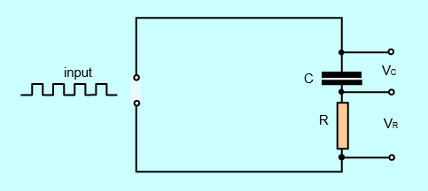
Student investigation
Investigate the smoothing effects of the circuit in the circuit below in which a square wave is applied to a capacitor and resistor in series.
Record both the input waveform and the waveform across the capacitor for various capacitances.
A VERSION IN WORD IS AVAILABLE ON THE SCHOOLPHYSICS CD