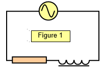
The LR (inductance-resistance) circuit
The circuit in Figure
1 contains both inductance and resistance. As with the capacitance-resistance circuit, the
current through it depends on the value of both the components and the frequency of the supply
voltage.
Let the supply voltage
be v0 and the voltages across the inductor and the resistor be vL0 and vR0 respectively. Now we
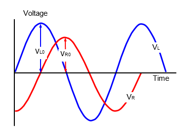
know that for a resistor the current and voltage are in phase, while for an inductor the current
leads the voltage by 90o; VL0 therefore leads v0 by 90o, as can be seen from Figure 2.
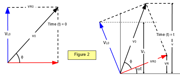
The resultant voltage is
given by
v
02=
v
R02 + v
L02 =
i
02R
2 + i
02X
L2
The current in
the circuit is therefore: i
o =v
o/[X
L2 + R
2]
1/2
and the impedance (Z) is:
Z = [XL + R2]1/2 = [ω2L2 + R2]1/2
The phase angle for this circuit (φ) (see Figure 3) is given by
tanφ = vL0/vR0 = -ωL/R
A VERSION IN WORD IS AVAILABLE ON THE SCHOOLPHYSICS CD