The L-C-R series circuit
The circuit shown in Figure 1(a) contains all three
components in series. In the vector diagram in Figure 1(b), notice the directions of the voltage
vectors showing the phase differences between them and the resultant voltage.
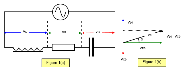
The voltages across the
inductor and the capacitor (v
L0 and v
L0) are 180
o out of phase, and the result of the
addition of these two must be added vectorially to V
R0 to give the resultant voltage, which is
therefore given by:
v02 = (vL0 – vC0)2 +
vR02 = (i0XL – i0XC)2+
i02R2
This means that the impedance of the circuit is:
Impedance of LCR circuit: Z = [(XL-XC)2+R2]1/2 = [(wL -1/ωC)2+R2]1/2
It should be
realised that since the voltages across the capacitor and inductor are 180
o (
p) out of phase they
may be individually greater than the supply voltage – see the following
example.
Example problem
Consider an L-C-R series circuit where R = 300 Ω, L = 0.9 H, C = 2.0 μF and the supply frequency has a frequency of 50 Hz and an r.m.s. voltage of 240 V.
Therefore ω: = 2πf = 2 x π x 50 = 314 radians per second.
XL = ωL =314 x 0.9 = 2830 Ω
XC = 1/ωC = 1/[314x2x10-6] = 1592 Ω
The reactance X of the capacitor-inductor components is 1592 - 283 = 13090 Ω.
The reactance Z is given by:
Z = [x2 + R2]1/2 = 13420 W
The phase angle will be 77o and the current in the circuit 0.18 A.
Summarising:
For the resistor : vR = IR =0.18x300 = 54V
For the inductor: vL = iXL = 0.18x283 = 51V
For the capacitor: vC = iXC = 0.18x1592 = 287V
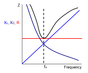
Resonance
One very important consequence
of this result is that the impedance of a circuit has a minimum value when X
L = X
C. When this
condition holds the current through the circuit is a maximum.
This is known as the resonant
condition for the circuit. You can see that since X
L and X
C are frequency-dependent, the
resonant condition depends on the frequency of the applied a.c.
Every series a.c.
circuit has a frequency for which resonance occurs, known as its resonant frequency (f
o). This is
given by the equation
1/2πfoC = 2πfoL
Resonant frequency (fo) = 1/2π[LC]1/2
For the circuit given in the above example the resonant frequency is 119Hz.
(see also the example below).
Figure 2 shows how X
L,X
C, R and Z vary with frequency
for a series circuit. The value of f
o is clearly seen.
By using a variable capacitor as a
tuner in a radio circuit different stations may be picked up. The large current at resonance being
fed to an amplifier and finally to operate the
loudspeaker.
Example problems
A capacitor of 20 pF and an inductor are joined in series. Calculate the value of the inductor that will give the circuit a resonant frequency of 200 kHz (Radio 4).
Resonant frequency (fo) = 2 x 105 = ˝π[LC]1/2
Therefore:
L = 1/4 x 1010 x 20x10-9 x 4π2 = 0.03 mH
A VERSION IN WORD IS AVAILABLE ON THE SCHOOLPHYSICS CD