The oscillations of the current within an electrical circuit are of fundamental
importance in the generation of waveforms of a variety of shapes for radio, oscilloscopes, signal
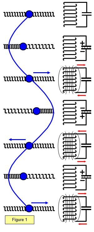
generators and so forth. One of the simplest circuits for producing these oscillations is a
capacitor and an inductor connected as shown in Figure 1. In understanding these oscillations it
is helpful to compare them with the mechanical oscillations in a spring.
The mass on
the spring oscillates, transferring stored potential energy in the spring to kinetic energy of the
mass and back again. The charge in the electrical circuit also oscillates, transferring stored
energy in the electric field of the capacitor to energy in the magnetic field in the inductor.
(a) This diagram represents the initial zero energy situation for both systems. The mass is at rest
and the springs are in equilibrium and no energy exists as stored charge in the capacitor or current in the
inductor.
(b) The mass is displaced from its rest position, and therefore potential energy is
stored in the spring. The capacitor is charged, thus possessing potential energy.
(c) As soon
as the mass is released it moves to the right, gaining kinetic energy. The capacitor begins to
discharge through the inductor, producing a current in it.
(d) The mass is now at rest; all the
energy is stored as potential energy in the spring. The charge has now stopped moving and all
energy is stored in the capacitor, which is charged in the opposite sense from its original
state.
(e) This process now repeats itself, the mass oscillating backwards and forwards and
the charge continually charging and discharging the capacitor.
A continuous exchange of
energy occurs from potential to kinetic energy in the springs ˝Fe going to ˝mv2and in
the electrical circuit ˝ QV going to ˝ Li2
The amplitudes of the oscillations decrease with
time, since energy is lost as other forms: (a) in the spring as heating in the coils and air
resistance, (b) in the inductor and connecting wires as heat due to the flow of current within
them.
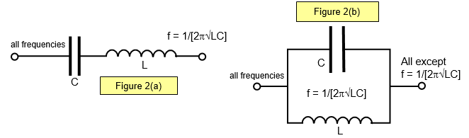
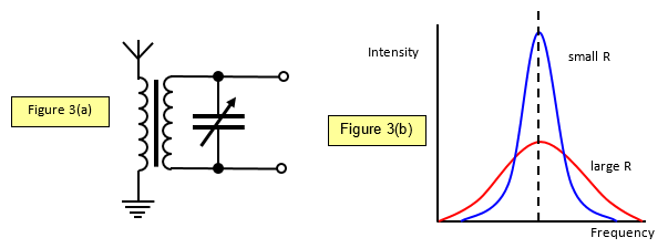
If the capacitor (or inductor) is variable, then the circuit may be tuned to resonate at a particular frequency. This is used in the tuning of a radio set. The aerial receives a broad hand of frequencies and the capacitor is varied so that the circuit resonates at the frequency of the required station. A simple circuit for the tuner section of a radio receiver is shown in Figure 3(a). The response of the circuit with frequency is shown in Figure 3(b), in which R is the total series resistance of the tuned circuit.