The PV cycle for an ideal gas – the Carnot cycle
Tbe concept of
the ideal heat engine was first developed by the French scientist Sadi Carnot in 1824. He
imagined an engine that was free from friction and where the working substance, usually a
gas, was taken through a completely reversible cycle consisting of two isothermal and two
adiabatic changes.
Figure 1(a)
AB ISOTHERMAL
EXPANSION at temperature T
1. To keep the temperature constant an amount
of heat energy (Q
1) must be
ADDED to the gas
BC ADIABATIC
EXPANSION - no heat enters or leaves the system and so the temperature falls from
T
1 to T
2.
CD ISOTHERMAL COMPRESSION at temperature
T
2. To keep the temperature constant heat energy (Q
2) must be
REMOVED from the gas at a temperature T
2. Notice that T
2 is LESS
then T
1.
DA ADIABATIC COMPRESSION - no heat enters or leaves
the system and so the temperature rises from T
2 to T
1The area in the
closed loop is the
WORK DONE BY THE
GAS
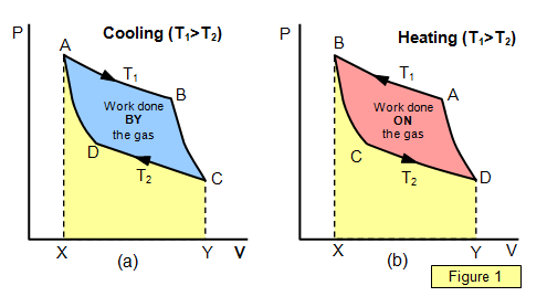
Figure 1(b)
AB ISOTHERMAL COMPRESSION at temperature
T
1. To keep the temperature of the gas constant heat a quantity of heat energy
(Q
1) must be
REMOVED from the gas at a temperature
T
1.
BC ADIABATIC EXPANSION - no heat enters or leaves the system
and so the temperature falls from T
1 to T
2CD ISOTHERMAL
EXPANSION at temperature T
2. To keep the temperature of the gas constant a
quantity of heat energy (Q
2) must be
ADDED to the gas at a temperature
T
2. Notice that T
2 is LESS then T
1.
DA ADIABATIC
COMPRESSION - no heat enters or leaves the system and so the temperature rises
from T
2 to T
1.
The area in the closed loop is the
WORK DONE ON THE GAS.
The direction round the
loop is all-important. This decides whether the system is operating as a heater or a
refrigerator.
The work done by the gas is given by the area ABCYXA and the work done
on the gas is given by the area CDAXYC. The net work done by the gas is therefore
represented by the area ABCD.