COUNTING CIRCUITS
If we
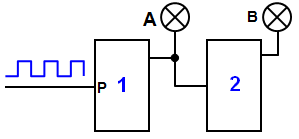
connect two or more clocked bistables in series then we have a
COUNTING
CIRCUIT.
The output of bistable 1 is connected to the input of bistable 2. When
pulses are applied to the input of bistable 1 its output changes every time a falling edge
occurs at the input, in other words half as often as the input.
This signal is now
applied to the input of bistable 2 and so the output of bistable two changes one quarter as
often as the input to bistable 1.
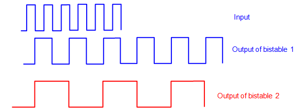
It is much easier to see this on the diagram.
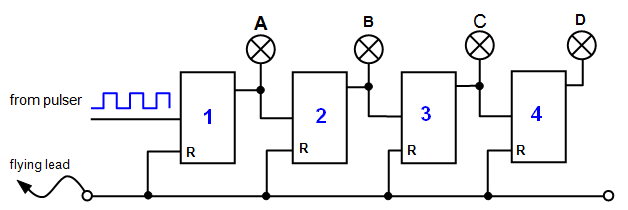
Now we
will consider applying pulses one at a time from the pulser to the input of the first of four
clocked bistable units and look at the outputs of each one. The output of each bistable is
connected to an LED.
The table below shows what will happen as one pulse after
another is applied. To understand what is going on remember that the output of any clocked
bistable will only change when the falling edge of a pulse is applied to its input (ie the LED
will either come on or go off).
Output of the
counting unit
| Pulse number |
D |
C |
B |
A |
|
Pulse number |
D |
C |
B |
A |
| 0 |
0 |
0 |
0 |
0 |
|
8 |
1 |
0 |
0 |
0 |
| 1 |
0 |
0 |
0 |
1 |
|
9 |
1 |
0 |
0 |
1 |
| 2 |
0 |
0 |
1 |
0 |
|
10 |
1 |
0 |
1 |
0 |
| 3 |
0 |
0 |
1 |
1 |
|
11 |
1 |
0 |
1 |
1 |
| 4 |
0 |
1 |
0 |
0 |
|
12 |
1 |
1 |
0 |
0 |
| 5 |
0 |
1 |
0 |
1 |
|
13 |
1 |
1 |
0 |
1 |
| 6 |
0 |
1 |
1 |
0 |
|
14 |
1 |
1 |
1 |
0 |
| 7 |
0 |
1 |
1 |
1 |
|
15 |
1 |
1 |
1 |
1 |
Pulse 2 switches off output 1, ie after two pulses to clocked bistable number 1
LED B comes on.
The right hand column shows the number of pulses as a four bit
binary number. In other words the four clocked bistables act as a four bit binary
counter.
You can see that this is a counting circuit that will count up to a certain
number of pulses until all LEDs are on.
A RESET lead would be useful if this was
used as a practical counting circuit so that you could do another count.
A VERSION IN WORD IS AVAILABLE ON THE SCHOOLPHYSICS USB