
The cathode ray oscilloscope (CR0) is a very useful instrument that has many
applications in science.
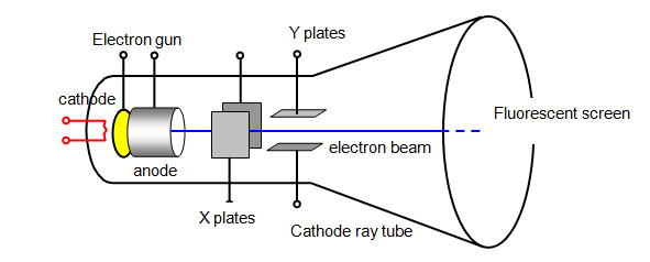
A beam of electrons is shot down an evacuated tube by an
electron gun. This beam passes between two sets of deflecting plates and then strikes a
screen that glows when the beam hits it (fluorescence).
The most important parts
of the CR0 are:
(a) electron gun - this produces the electron beam. The more electrons
there are in the beam the brighter the spot on the screen;
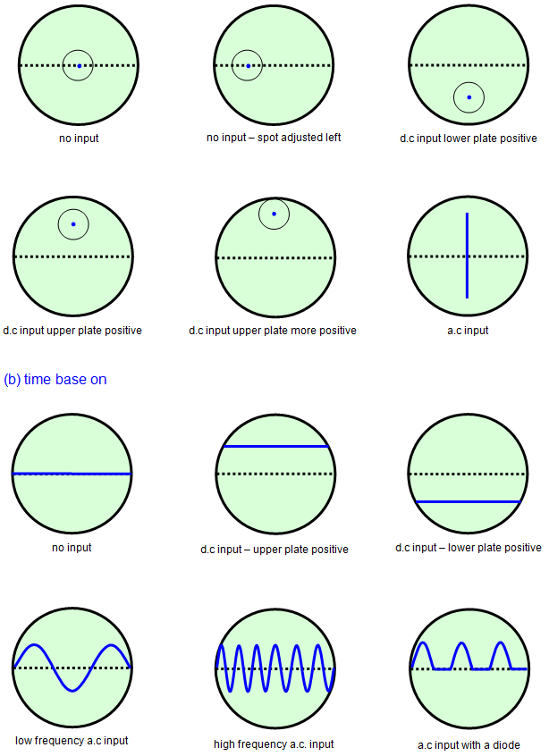
(b) deflecting plates - by
putting a voltage on each pair of plates the beam can be moved up and down or side to
side.
Since the electron beam is negative it will be attracted towards a positive
plate;
(c) fluorescent screen - this glows when the electron beam hits it.
You
will find various controls on the front of an oscilloscope, this is what they do:
On/Off-
obvious
Brightness - makes the beam brighter, this is sometimes linked to the on/off
control
X shift - moves the spot across the screen
Y shift - moves the spot up and
down the screen
X gain - magnifies movement in the X direction
Y gain - magnifies
movement in the Y direction
Focus - obvious
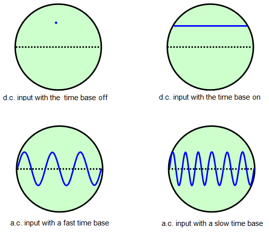
Time base - makes the spot move
from one side of the screen to the other at various speeds. Usually from 1 second to 1
millionth of a second for one crossing.
There are other controls but we will not
deal with them here, but the time base is worth looking at more closely.
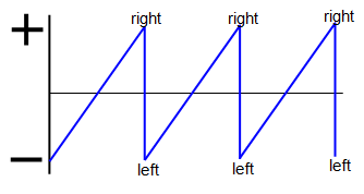
A voltage is applied to the X plates
that pulls the spot across the screen, allows it to fly back again by changing sign and then
pulls it across again, and so on. The voltage is called a SAW TOOTH wave and is shown
in the diagram below. The bigger the voltage the further the spot gets pulled across, and
the greater the frequency the faster it moves.
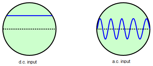
The input voltage is
usually connected to the Y plates and this pulls the spot up and down as the time base
moves it across the screen.
The following diagram shows you various patterns
that can be made on the screen with two different inputs.