
Inductive circuits
Like a capacitative circuit, a pure inductive circuit behaves
quite differently from one containing resistance alone. Consider the circuit in Figure 1.
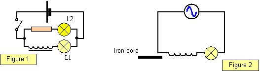
When the switch is closed the
lamp (L1) in series with the inductance lights more slowly than lamp L2 suggesting that the
inductance resists a changing current.
A coil with an iron core has a much greater
inductance than one with an air core, and using the circuit in Figure 2 you can show that the
lamp will dim markedly or even go out when the iron core is placed in the coil. If d.c. were used,
however, the lamp would remain alight whether there was an iron core or not.
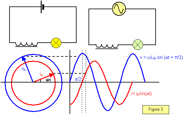
In the inductive circuit the current and voltage are not in phase; in fact, the current lags behind the voltage by 90
o as shown by the
vector diagram in Figure 3.
In inductive circuits the voltage leads the current by 90o (p/2)
This can be shown mathematically as follows.
Let the current flowing through an inductance L be i= I
0sin(
wt)
Now the back e.m.f. produced is E = - Ldi/dt = -
wLi
0 cos(
wt)
The applied p.d. is therefore:
-E = v =
wLi
0cos(
wt) =
wLi
0sin
w(t +
p/2)
This shows that the voltage leads the current by
90
o or
p/2.
An easy way of remembering
the lead and lag is to use the word
CIVIL.
Capacitance – current (I) leads voltage; Inductance voltage leads current (I)
A VERSION IN WORD IS AVAILABLE ON THE SCHOOLPHYSICS USB