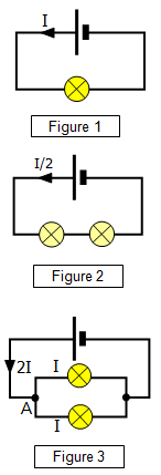
In the series circuit the potential is shared between the two
bulbs and so the potential difference across each bulb is only half that across the single bulb
in Figure 1. The current is therefore half what it was Figure 1 if the bulbs are all the same.
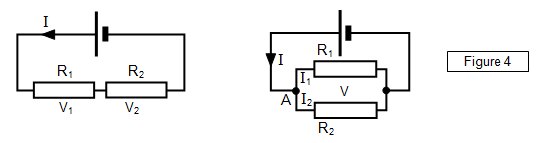
This means that the RESISITANCE of two components (bulbs or resistors) in series is
GREATER than that for a single component.
Series circuits are often used for
Christmas tree lights – lots of low voltage bulbs in series are run from the mains. For
example 100 2.5V bulbs can be connected together in series and run safely and at normal
power from the 240V mains – the voltage drop across each bulb is
2.4V.
Parallel
In a parallel circuit the potential across each bulb is the
same as it was in the circuit with the single bulb. Each bulb in the parallel circuit 'feels' the full
potential difference across it. The current flowing through each bulb is therefore the same as
that through the single bulb. If the bulbs are all the same the current flowing from the cell will
be double that for the single bulb.
This means that the RESISITANCE of two
components (bulbs or resistors) connected in parallel is LESS than that of a single
component.
Bulbs connected to a cell in series will run the cell down slower than if
they are connected in parallel.
The increase in the current flowing from the cell in a parallel circuit is
really important when you are using adapters or multiple outlet socket boards at home. If you
connect two appliances to an adapter, each of which might take 4A when connected to the
mains socket on its own the total current flowing into the adapter from the mains is 4A.
Connecting another appliance that also takes 4A to a three-way adapter means a total
current flowing into the adapter of 12A. This is close to the maximum (13A) that the circuit
can stand without blowing the fuse.
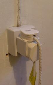
The photograph shows an adapter used with
two outlets – one is to an iron taking about 3A while the other is to a washing machine taking
about 2A. This is safe. However a further danger with adapters is forgetting to unplug one of
the appliances when you switch on. You might want to use the washing machine but not
want to have the iron on! It is better not to use adapters or multiple outlet plug boards unless
you are sure what is plugged into them.
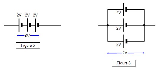
Cells can also be connected in
series or parallel.
If a number of cells are connected in series the total potential
difference between the ends of the chain is the sum of the potentials differences across each
cell (Figure 5). Each cell gives each coulomb some energy as it passes through it. You often
find two 1.5V cells placed in series in a torch to give a total output to the bulb of
3V.
If the cells are connected in parallel (Figure 6) the total potential difference
across the arrangement is the same as for one cell. Electricity flowing round the circuit can
only pass through one cell and so each coulomb can only gain energy from that cell. The
advantage of the parallel circuit is that although the output voltage is the same as that of a
single cell the battery formed from the group of cells contains more energy and so will supply
current for longer.